This article goes over how an AI model could theoretically be built to regenerate 3D meshes from 2D image inputs. It will be presented in a step-by-step order. I am not an AI developer or expert. I am only an expert in 3D design; so this is how I would do it if there was a “plug and play” machine learning (ML) system that handled creating the neural network for me.
I want to put this concept out there so that if any well-financed companies end up using a similar system, I can point to this article and say “see, I know what I’m talking about. Someone should pay me to implement my ideas!”.
If no one ends up using this system or it ends up being completely unworkable I can then point to it and say “see, if only I had more funding, I would have been able to refine this idea before publishing it!”.
Basically, I want money to build the future. Money please.
Step One: Segmentation
Each image would be broken apart via image and object classification. This is a pretty solved issue; you can even build your own image classification using Google’s Teachable Machines.
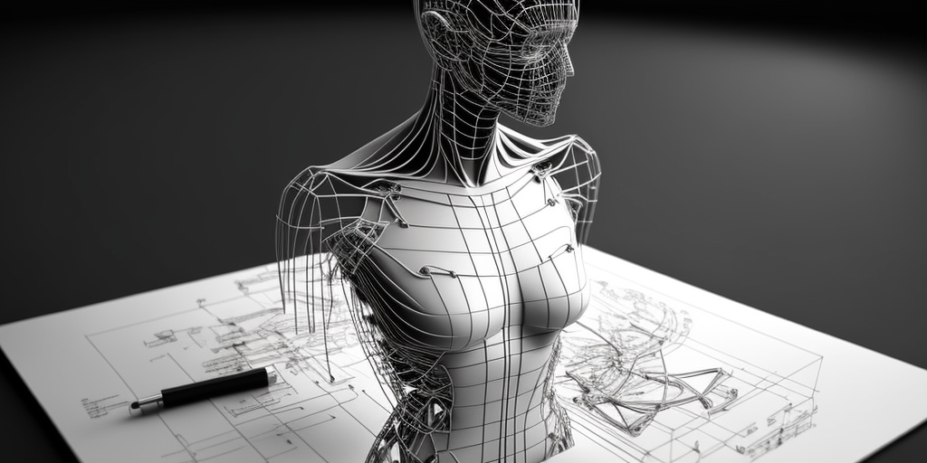
Moses Olafenwa even shows you how to do it using ten lines of code in this Medium article, which is where the image to the right comes from.
If there is only one object in the image then this classification step could be used to save on further processing time by selecting from a dataset that is most similar to the identified object.


Step Two: 2D Meshing
Once the objects are split out, they each go through the following steps individually.
The object’s boundaries are determined via image reconstruction algorithms. This creates the outline for the object, which is then filled with a randomized pattern of vertices to create a flat, 2D mesh.

Step Three: Depth Calculation & Vertex Displacement
A depth map is created from the image. In a depth map, white is close and black is far. This is also a solved problem – see this tutorial by Blender Smoothie 3D.
The depth map is then applied to the mesh from the previous step. See the results in the GIF below.


Step Four: Neural Analysis
The offset vertices and resultant surface are compared to a training set of 3D models. The model where the offset vertices are closest to the trained surface is chosen and an adjustable parameter allows for the model to prefer the training data or the offset vertices, where weighting one or the other will pull the reconstructed mesh closer to the pre-trained surface.

Followup
A challenge here is to account for object rotation. I propose that this can be solved by one of the following methods;
- Pre-training the model on the vertex positions of reference objects in different orientations, then trying to find the most consistent fit.
- Rotating the constructed model through a series of probabilistic orientations based on schema (for example; cars are unlikely to be viewed from below) until the model finds the best fit.
- Determining a rough object orientation during the image segmentation phase and then comparing the reconstruction against the trained data in that orientation.
Doubtlessly; there are issues with these approaches and there are others that I have not thought of. But I think this might be at least a good starting point.
Additionally, I think that a good training set would be industrial-design style drawings. This is because this drawing has a standardized language, where external outlines are thick and bold, internal outlines are solid and contour lines are lightweight. Often the objects are also drawn in an X-Ray style. By starting with a standardized 2D approach I believe it would be easier to create a reliable 3D output.

So what do you think? Comment below if you think this makes any sense – or if you think it doesn’t!